")
")


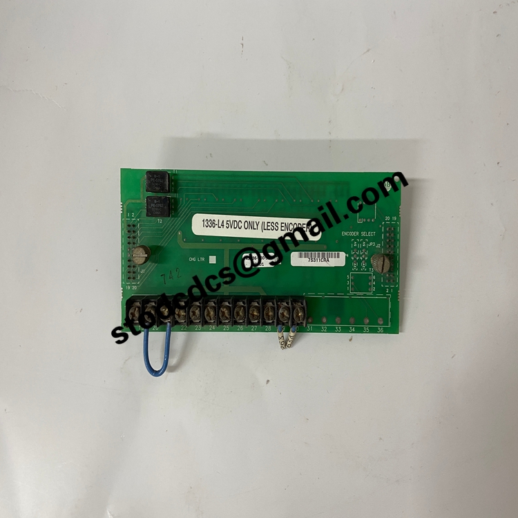
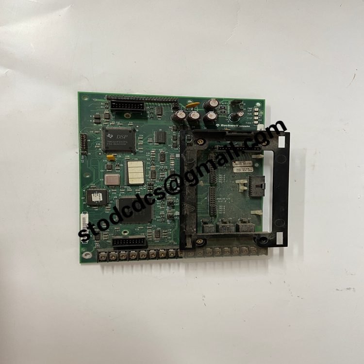
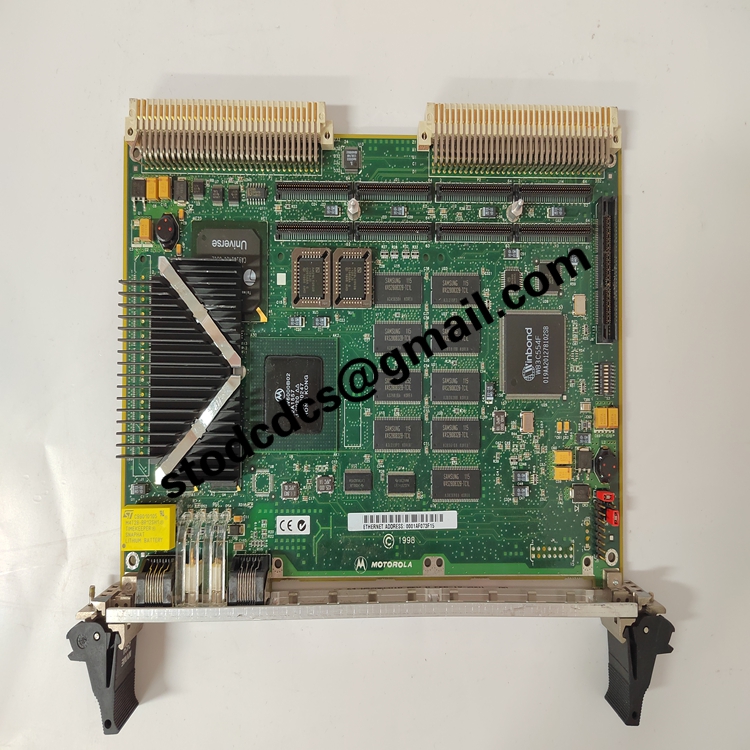
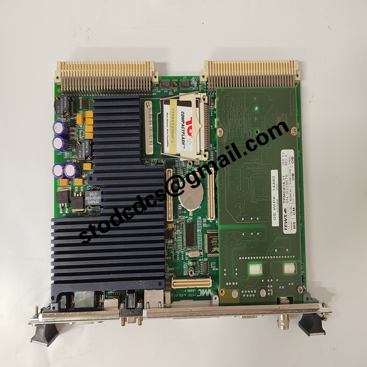
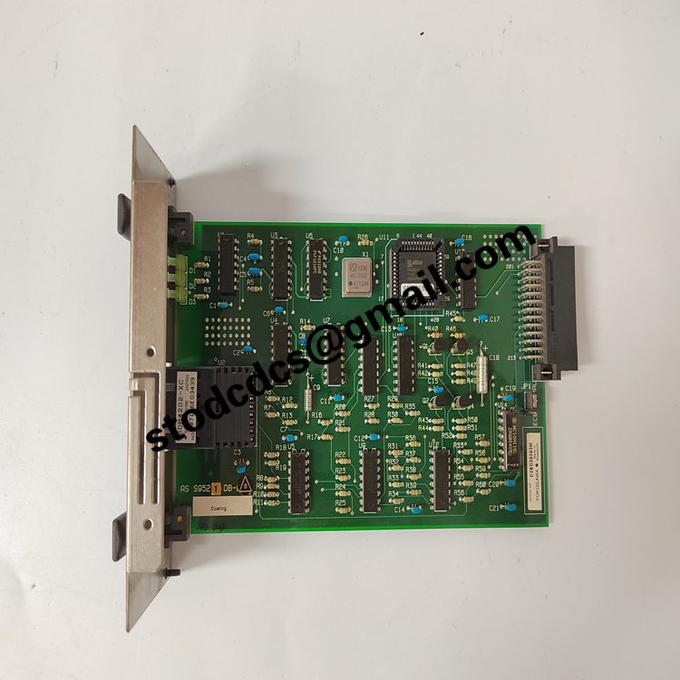
193X537ADG01 DC Drive Main Control Board
Product manual:
GE 193X537ADG01 is the Main Control Board introduced by General Electric in its 193X series DC drive control system.
This board plays a core role in the GE DC drive system,
Technical specifications and functional features
Product type: DC drive main control board
Control method: Combining analog signal regulation with digital control logic
Input signals: including voltage, current, speed feedback, encoder signals, etc
Output signals: control the driving signal, feedback signal, alarm signal, etc. of the power module
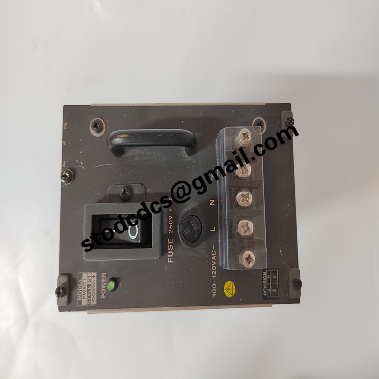
Power requirement: The typical operating voltage is ± 15V DC (provided by the system power supply)
Signal input and output: Supports analog input (such as speed, current feedback)
Digital signal input (such as switch contacts, start commands)
Component configuration: including high-precision resistors, potentiometers, transistors
Operational amplifiers and other core components used to achieve precise control
Working temperature: The typical working temperature range is -20 ° C to+70 ° C
application area
GE DC drive system: such as GE Mark I, II, IV series motor control systems
Motor control and speed regulation system: mainly used for speed regulation and excitation control of DC motors
Industrial automation: widely used in industries such as metallurgy, power, petrochemicals, and papermaking
Replacement and Upgrade: Used for the maintenance and upgrade of outdated control systems,
Replace the old control board to improve system reliability
Installation and commissioning precautions
Preparation before installation:
Confirm that the system power supply voltage meets the requirements (usually ± 15V DC)
Be sure to turn off the power during installation to avoid damage to the circuit board or the risk of electric shock
Wiring and installation:
Ensure good connection with the mainframe and other control modules to prevent signal loss or poor contact
All input and output signal wiring should be strictly connected according to the control system design drawings
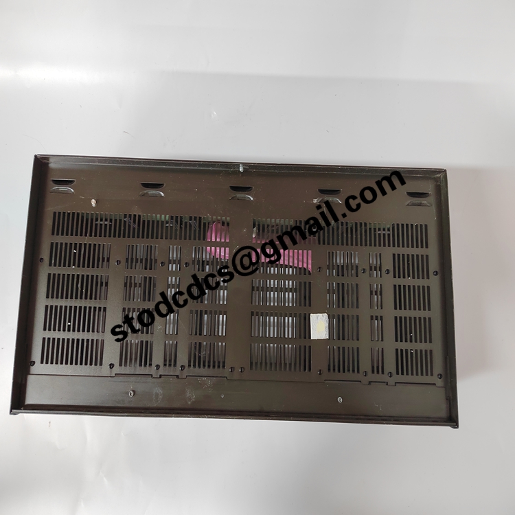
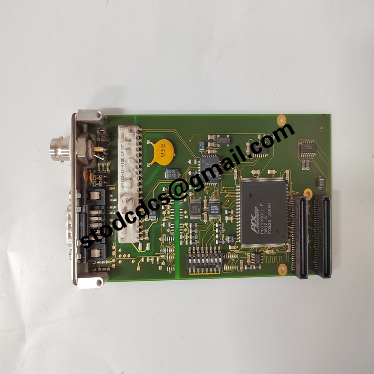
Product details picture:
More related products:
6ES7315-2AF83-0AB0CentralProcessingUnit
VME7865RC350-9300007865-230003Busmodule
More product recommendations:
GE IS210BPPBH2CAA Printed Circuit Board